3D Double Compound Pendulum
Simulation of a double compound pendulum in 3D using MATLAB.
Overview
In my previous post, I simulated a single compound pendulum in 3D. In this post, I will be extending this to a double compound pendulum in 3D. I will be using the Lagrange method only. Although the Newton-Euler method will not be explored in this post, it is not conceptually any different than what was done for the single pendulum. The only additional complexity would be that there will be additional reaction forces and moments on the first pendulum. Just as in the single pendulum, the two pendulums will not be allowed to twist about their longitudinal axes.
Lagrange Method
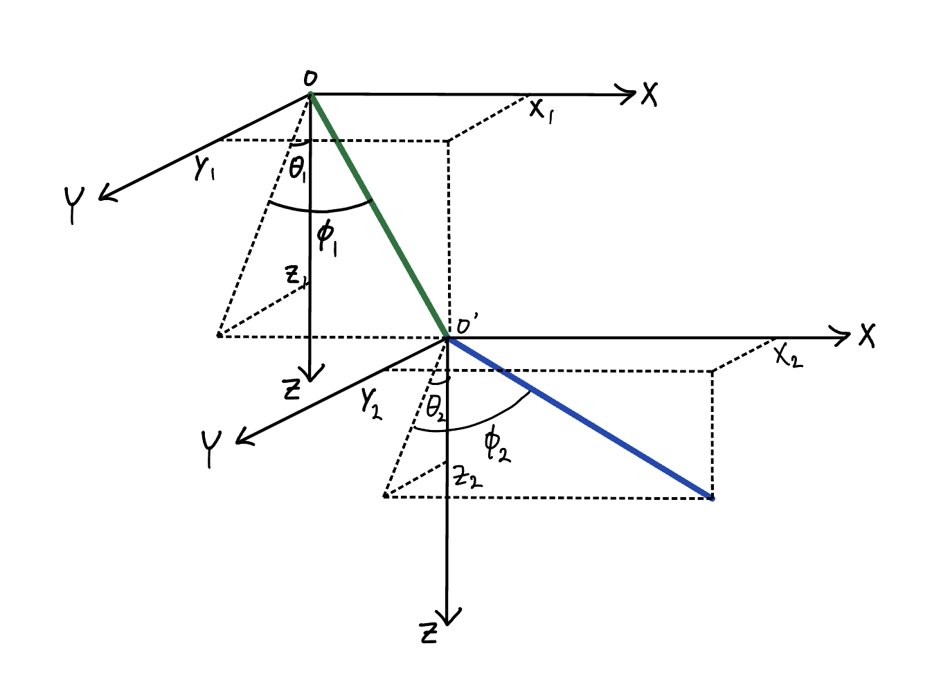
In general, it takes a total of twelve coordinates to fully describe a system with two rigid bodies. Six of these describe the position of the two bodies and the other six describe the orientation of the two bodies. Constraining the first pendulum to be rigidly attached to the base and constraining the second pendulum to be rigidly attached to the first pendulum reduces this to six coordinates. The no-twist condition further reduces this to four coordinates.The four coordinates will be defined as \(\theta_1\), \(\phi_1\), \(\theta_2\), and \(\phi_2\) (see figure below).

We will assume that the two pendulums have the same mass, length, and moments of inertia.
Recall that the Lagrangian of the system is given by:
\[L = T - V\]where \(T\) is the kinetic energy of the system and \(V\) is the potential energy of the system.
First, we’re going to derive an expression for the kinetic energy of the system in terms of \(\theta_1\), \(\phi_1\), \(\theta_2\), and \(\phi_2\). But before we can do so, we need to define two body frames \(B_1=(\hat{b}_{1,1},\hat{b}_{1,2},\hat{b}_{1,3})\) and \(B_2=(\hat{b}_{2,1},\hat{b}_{2,2},\hat{b}_{2,3})\). Frame \(B_1\) pertains to the first pendulum and frame \(B_2\) pertains to the second pendulum. The process of deriving the coordinate transformation matrices is the same as in the single pendulum case.
The kinetic energy of the double pendulum system is given by:
\[T = \frac{1}{2}m(v_{1,x}^2+v_{1,y}^2+v_{1,z}^2)+\frac{1}{2}(I_1\omega_{1,1}^2+I_2\omega_{1,2}^2+I_3\omega_{1,3}^2)+\frac{1}{2}m(v_{2,x}^2+v_{2,y}^2+v_{2,z}^2)+\frac{1}{2}(I_1\omega_{2,1}^2+I_2\omega_{2,2}^2+I_3\omega_{2,3}^2)\]Whenever there are two subscripts, the first subscript will refer to which of the two pendulums and the second subscript will refer to the which component. So for example, \(v_{1,y}\) is the \(\hat{y}\) component of the velocity of the center of mass (COM) of the pendulum 1 and \(\omega_{2,1}\) is the \(\hat{b}_1\) component of the angular velocity of pendulum 2.
As in the single pendulum case, the angular velocity of the first pendulum is given by the following:
\[{}^I\mathbf{\omega}^{B_1}=-\dot{\theta}_1cos(\phi_1)\hat{b}_{1,1}+\dot{\phi}_1\hat{b}_{1,2}-\dot{\theta}_1sin(\phi_1)\hat{b}_{1,3}\]Likewise, the angular velocity of the second pendulum is given by the following:
\[{}^I\mathbf{\omega}^{B_2}=-\dot{\theta}_2cos(\phi_2)\hat{b}_{2,1}+\dot{\phi}_2\hat{b}_{2,2}-\dot{\theta}_2sin(\phi_2)\hat{b}_{2,3}\]The two equations above give us the angular velocity components that we need to compute the kinetic energy of the system. Next, we need to derive expressions for the COM velocity components of the two pendulums. For the first pendulum, the expression is the same as it was for the single pendulum case:
\[v_{1,x} = \frac{l}{2}\dot{\phi}_1cos(\phi_1)\] \[v_{1,y} = -\frac{l}{2}\dot{\phi}_1sin(\theta_1)sin(\phi_1)+\frac{l}{2}\dot{\theta}_1cos(\theta_1)cos(\phi_1)\] \[v_{1,z} = -\frac{l}{2}\dot{\phi}_1cos(\theta_1)sin(\phi_1)-\frac{l}{2}\dot{\theta}_1sin(\theta_1)cos(\phi_1)\]To compute the velocity components of the second pendulum, consider the position vector of the COM of the second pendulum:
\[\mathbf{r}_{G_2/O}=2\mathbf{r}_{G_1/O}+\mathbf{r}_{G_2/O'}\]Then the velocity of the COM of second pendulum is:
\[\mathbf{v}_{G_2/O}=2\mathbf{v}_{G_1/O}+\mathbf{v}_{G_2/O'}\]Consequently, COM velocity components of the second pendulum are the following:
\[v_{2,x} = l\dot{\phi}_1cos(\phi_1)+\frac{l}{2}\dot{\phi}_2cos(\phi_2)\] \[v_{2,y} = -l(\dot{\phi}_1sin(\theta_1)sin(\phi_1)-\dot{\theta}_1cos(\theta_1)cos(\phi_1))-\frac{l}{2}\dot{\phi}_2sin(\theta_2)sin(\phi_2)+\frac{l}{2}\dot{\theta}_2cos(\theta_2)cos(\phi_2)\] \[v_{2,z} = -l(\dot{\phi}_1cos(\theta_1)sin(\phi_1)+\dot{\theta}_1sin(\theta_1)cos(\phi_1))-\frac{l}{2}\dot{\phi}_2cos(\theta_2)sin(\phi_2)-\frac{l}{2}\dot{\theta}_2sin(\theta_2)cos(\phi_2)\]Now we have all of the pieces to get an expression for the kinetic energy of the system.
The next step is to obtain expressions for the potential energies of the two pendulums:
\[V = -mgz_1 - mgz_2=-\frac{mgl}{2}cos(\phi_1)cos(\theta_1)-mglcos(\phi_2)cos(\theta_2)\]Now that we have all of the pieces, We can use MATLAB’s symbolic toolbox to compute the Lagrangian. Then, finally, we can obtain the equations of motion by plugging in \(L\) into the Euler-Lagrange equation:
\[\frac{d}{dt}\left(\frac{\partial L}{\partial \dot{q}_i}\right)-\frac{\partial L}{\partial q_i}=0\]The generalized coordinates for this system are \(\theta_1\), \(\phi_1\), \(\theta_2\), and \(\phi_2\).
A compact way of writing the equations of motion is to use the built-in Jacobian function in MATLAB.
q = [theta_1 phi_1 theta_2 phi_2]';
q_dot = [theta_dot_1 phi_dot_1 theta_dot_2 phi_dot_2]';
q_ddot = [theta_ddot_1 phi_ddot_1 theta_ddot_2 phi_ddot_2]';
EoM = jacobian(jacobian(L,q_dot),q_dot)*q_ddot+jacobian(jacobian(L,q_dot),q)*q_dot-jacobian(L,q)' == 0;
Then we can solve for \(\ddot{\theta_1}\), \(\ddot{\phi_1}\), \(\ddot{\theta_2}\), \(\ddot{\phi_2}\) using the solve function. Finally, we can store q_dot and q_ddot into a single vector, turn it into a MATLAB function using matlabFunction and plug it into the ode45 solver to solve for the motion of the double pendulum.
Here are the resulting animations of the solution with various initial conditions:
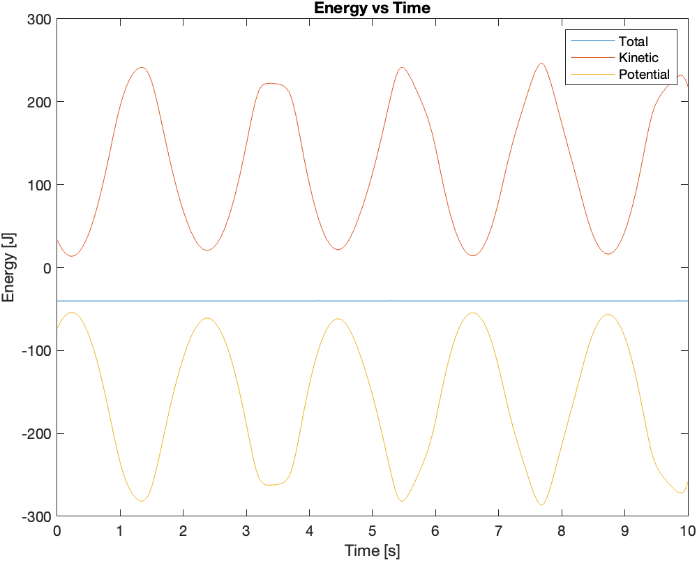
As a sanity check for the solutions, I plotted the energy versus time for the initial conditions corresponding to the second video:

From the plot, we can see that the total mechanical energy of the system is conserved. As for how to animate the solution, please refer to my previous post.