Classical Control of an Inverted Pendulum
Controller design for an inverted pendulum using classical control techniques.
Problem Setup
In this post, I am going to walk through how I approached the design of a controller for an inverted pendulum in the frequency domain. First, let’s start by exploring the open-loop dynamics of the inverted pendulum. The linearized equations of motion of the inverted pendulum about the upright position are given below:

where \(x_{c}\) is the position of the cart, \(\theta\) is the angle the pendulum makes with the vertical axis, \(M_{c}\) is the mass of the cart, \(M_{R}\) is the mass of the pendulum rod, \(L\) is the length of the pendulum rod, and \(I_{rot}\) is the motor’s moment of inertia.
The input into the system is \(f_{c}\), the force on the cart. But we don’t directly control \(f_{c}\). The actual control input that we get to choose is the voltage supplied to the cart’s motor, \(V\). \(f_{c}\) is given by the following equation:
\[f_{c}=\alpha_{1}V+\alpha_{2}\dot{x}_{c}\]where \(\alpha_{1}\) and \(\alpha_{2}\) are system parameters that were empirically determined and \(\dot{x}_{c}\) is the velocity of the cart (so the second term is a drag term).
The output of the system (i.e. the quantity we measure) is the following:
\[x=x_{c}-\frac{2}{3}Lsin(\theta)\]We really measured both \(x_{c}\) and \(\theta\) but since frequency domain analysis is limited to single-input single-output (SISO) systems, we effectively lump these two measurements to get a single output so that we can design our controller in the frequency domain. At this point, by lumping the two measurements into one, we are throwing away information because we don’t know how to use it. When we design a controller for the same system in state-space in the next post, we will see how both measurements can be used.
Now that both the input and the output have been defined, we can obtain the open-loop transfer function of the plant from \(V\) to \(x\). For brevity, I will skip the derivation.
\[G(s)=\frac{-14.7}{s(0.4396s^3+4s^2-12.3126s-98)}\]Controller Design
Given the open-loop transfer function, we can now begin to design the controller. Before getting started, the following is a list of performance requirements that the controller must satisfy:
- The gain of the controller C(s) should be below 85 dB for all frequencies
- The gain of the controller C(s) at \(10^4\) rad/s should be below 30 dB
- Phase margin \(\phi > 10^{\circ}\)
- Gain margin \(\vert GM \vert > 3 dB\)
- Disturbance rejection settling time \(T^{10\%}_{s} < 2s\)
- \(\vert p \vert < 80\) for all poles
- The controller must be proper.
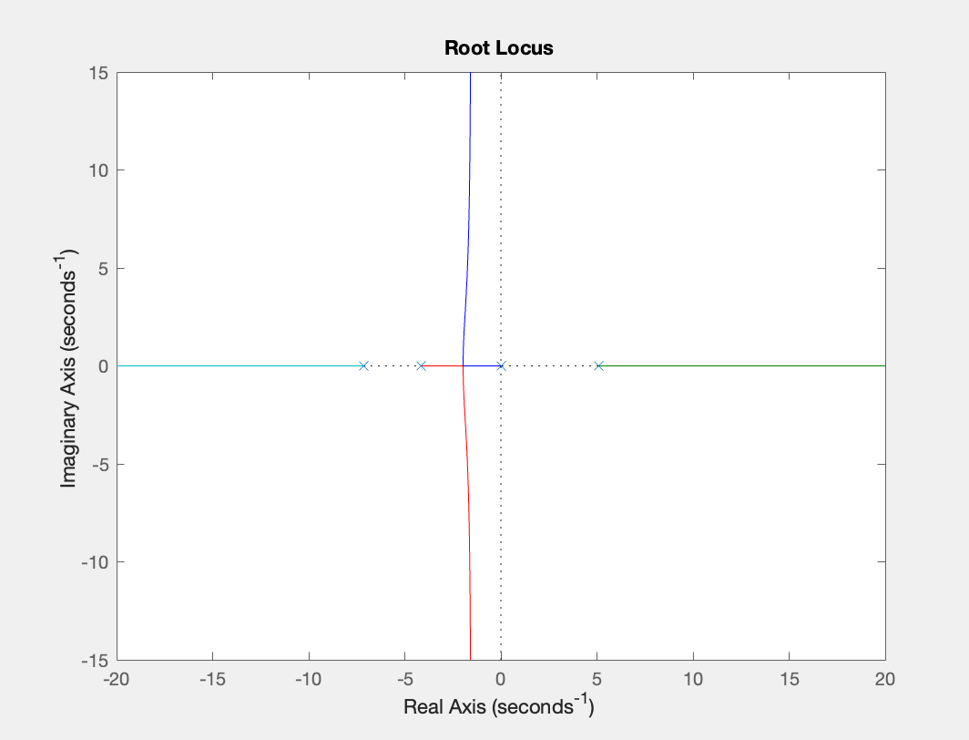
First thing we should do is look at the root locus of the open-loop transfer function to assess its stability:

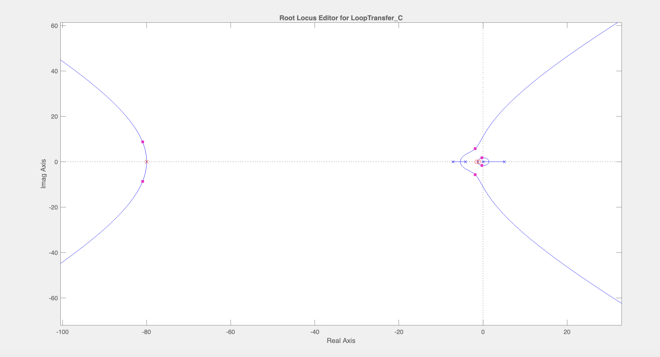
We can see from the root locus plot that the system has an open-loop pole in the RHP and is hence unstable. Then we should pull the root locus in the RHP into the LHP by placing zeros near the origin (because zeros “attract” poles). Let us place the two zeros at \(s=-1\) and \(s=-1.5\). To make the controller proper while not messing up the root locus around the two zeros we just placed, we will add two poles at \(s=-80\) far away from the rest of the pole/zeros. Then by adjusting the gain to -5, we are able to stabilize the system (i.e. pull the root locus into the LHP):


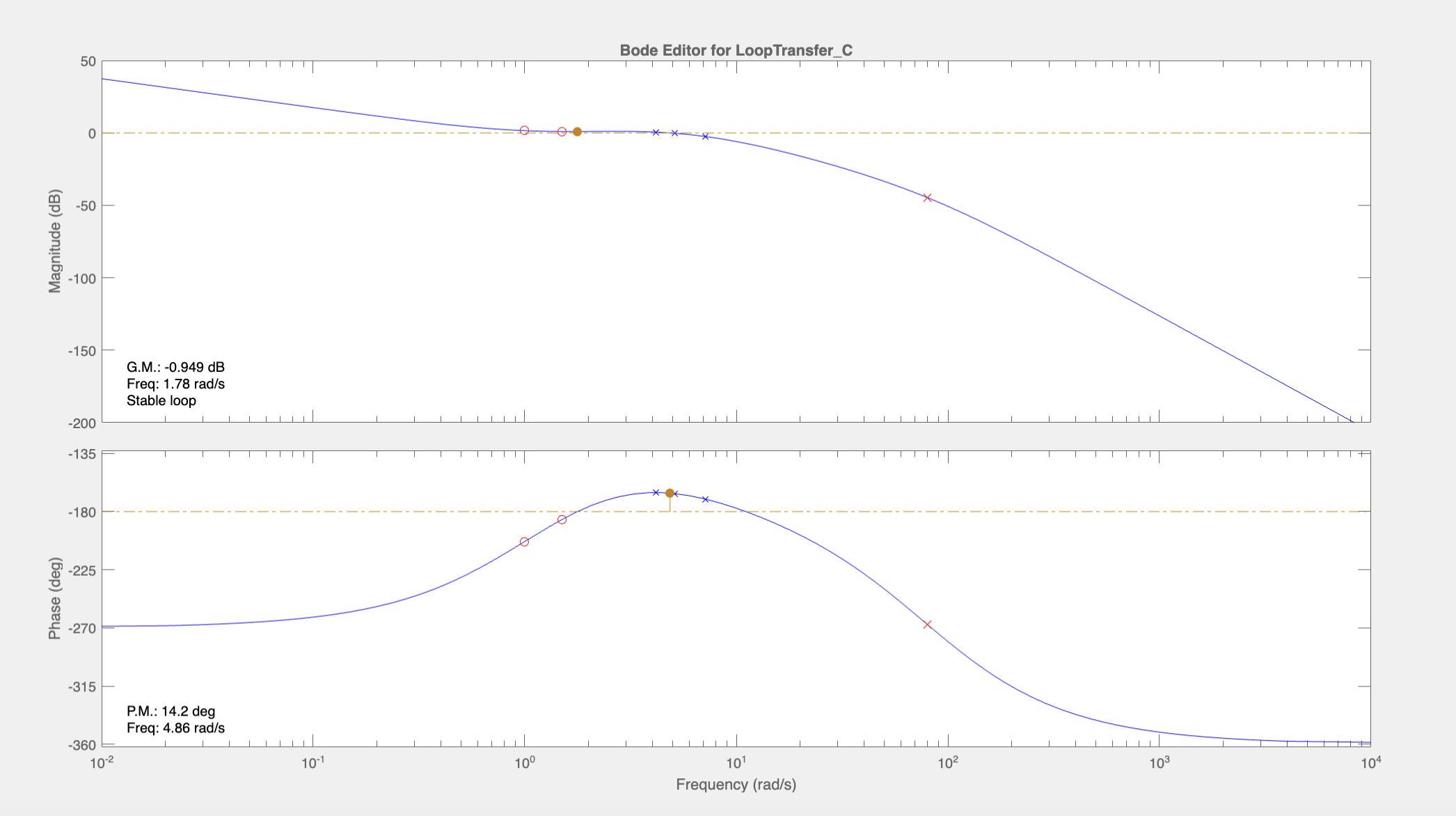
Notice that the magnitude plot near the cross-over frequency is very flat. This makes it difficult to control the crossover frequency by adjusting the gain. Ideally, we want the magnitude graph to decrease steadily near the crossover frequency. So, we should move the poles at 80 rad/s down closer to the crossover frequency to 30 rad/s to decrease the slope near the crossover frequency (~5 rad/s).

It’s still quite flat near the crossover frequency but we will come back to this later. At this point, the phase margin is 8.7 degrees which is too small. So, we can add another zero near the crossover frequency and add another pole at \(s=-80\) to make it proper while not affecting the region near the crossover frequency. We will choose to add a zero at \(s=-5\):

This boosted the phase margin to 45.6 degrees. Let’s check how we’re doing with the requirements on \(C(s)\). Below is a Bode diagram of \(C(s)\):

The magnitude of \(C(s)\) is too large especially at high frequencies. We can add a pole at \(s=-60\) to roll it off at high frequencies. This brings the maximum magnitude to about 90 dB and causes it to start rolling off at higher frequencies. To decrease it further, we will move two of the poles at \(s=-80\) to \(s=-60\) and \(s=-30\). This essentially “distributes” the gain over a larger range of frequencies. This brings the maximum magnitude down to about 83 dB.
Let us return to the task of getting rid of the flat part of the magnitude plot. We can do this by moving up the zero at \(s=-1.5\) to \(s=-5\). This effectively decreases the slope at 1.5 rad/s (by removing the +20 dB/dec slope introduced by the zero near that frequency). This also brought down the maximum magnitude of \(C(s)\) to around 73 dB. Now we have a nice steadily decreasing gain around the crossover which will allow us to control the crossover frequency by adjusting the gain:

We would like to move the crossover frequency to the point where the phase is at its peak. A gain of -11.5 seems to be adequate:

At this point, most requirements are satisfied but the controller \(C(s)\) does not satisfy the requirement that the gain be less than 30 dB at \(10^4\) rad/s. To roll off the gain of \(C(s)\) at \(10^4\) rad/s, we can place another pole at \(s=-80\). This satisfies the requirement on \(C(s)\) but at the same time, this decreases the phase margin to 6 degrees. To bring it back up, we can move the zero at \(s=-1\) to \(s=-0.5\) so that the phase increase from the zero aligns better with the peak of the phase such that we get a bigger peak (because phase bump from zero at \(s=0.5\) will now reach maximum at 5 rad/s rather than 10 rad/s). Then adjust the gain to -5.4 to align the crossover frequency with the frequency where the phase peak occurs. Here is the resulting Bode plot of the open loop transfer function:

The closed-loop system has a gain margin of 3.47 dB and a phase margin of 11.1 degrees.
Here is the resulting step response to a disturbance, showing a settling time less than 2 seconds:

The controller C(s) also satisfies the gain requirements:

The controller \(C(s)\) is given below:
\[C(s)=-5.4\frac{(1+2s)(1+0.2s)^2}{(1+0.017s)^2(1+0.033s)^2(1+0.013s)}\]Following is a video of this controller successfully stabilizing the inverted pendulum:
In the next post, I will walk through how I designed a controller using state-space methods to stabilized the same system.