3D Single Compound Pendulum
Simulation of a single compound pendulum in 3D using MATLAB.
Overview
One of the challenges of 3D rigid body dynamics is that the angular momentum vector is not always aligned with the angular velocity vector (as it is in the 2D case). In 3D, the two quantities are related by the inertia tensor. To study the complications of 3D rigid body dynamics, I simulated a compound pendulum in 3D. To simplify the math, the pendulum will not be allowed to twist about its longitudinal axis. This is equivalent to connecting the pendulum to the base via a universal joint.
I took two different approaches to solving for the motion of the pendulum: (1) Newton-Euler method and (2) Lagrange method. Both methods are fully explored in the sections below.
Newton-Euler Method
The Newton-Euler approach is the standard \(\sum \mathbf{F}=m\mathbf{a}\) (linear moment balance) and \(\sum \mathbf{M}=I\mathbf{\alpha}\) (angular momentum balance) approach to the problem. Furthermore, we will take the minimal coordinates approach, meaning that we will take into account the constraints to reduce the degrees of freedom of the system as much as possible prior to deriving the equations of motion. This is in contrast to the maximal coordinates approach where we allow the system to have maximal degrees of freedom and we introduce constraint equations only at the end, which must be solved simultaneously with the equations of motion.
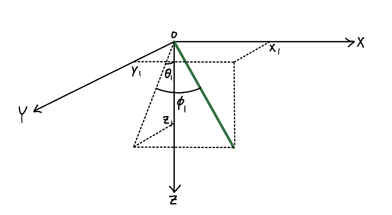
In general, you need six coordinates to fully describe the position and orientation of a rigid body in 3D space (three for position and three for orientation). Constraining the pendulum to be rigidly attached to the base reduces this to three coordinates (three angles). The no-twist condition further reduces this to two. We will define these two angles as \(\theta\) and \(\phi\), as shown in the figure below. Hence, solving for the motion of the pendulum boils down to solving for the time evolution of these two angles.
First, we need to define the body frame. To define the body frame, we need to go through a series of two rotations. We start with the inertial frame \(I=(\hat{x},\hat{y},\hat{z})\) and rotate it about \(\hat{x}\) by an angle \(\theta\) to obtain an intermediate frame \(A=(\hat{a}_1,\hat{a}_2,\hat{a}_3)\).
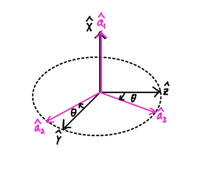
Notice that we defined the clockwise direction as the direction of positive rotation. Using simple geometric relations, we can write the relationship between the unit vectors of the two frames:
\[\hat{x}=\hat{a}_1\] \[\hat{y}=cos(\theta)\hat{a}_2+sin(\theta)\hat{a}_3\] \[\hat{z}=-sin(\theta)\hat{a}_2+cos(\theta)\hat{a}_3\]We can put the three equations into a matrix \({}^IC^A\), called the coordinate transformation matrix from frame \(I\) to frame \(A\):
\[{}^IC^A= \begin{bmatrix} 1 & 0 & 0 \\ 0 & cos(\theta) & -sin(\theta) \\ 0 & sin(\theta) & cos(\theta) \\ \end{bmatrix}\]For the second rotation, we rotate frame \(A\) about \(\hat{a}_2\) by an angle \(\phi\) to obtain the body frame \(B=(\hat{b}_1,\hat{b}_2,\hat{b}_3)\).
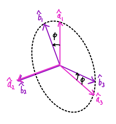
Again, we can write the relationship between the unit vectors of the two frames:
\[\hat{a}_1=cos(\phi)\hat{b}_1+sin(\phi)\hat{b}_3\] \[\hat{a}_2=\hat{b}_2\] \[\hat{a}_3=-sin(\phi)\hat{b}_1+cos(\phi)\hat{b}_3\]Then the transformation matrix from frame \(A\) to frame \(B\) is:
\[{}^AC^B= \begin{bmatrix} cos(\phi) & 0 & -sin(\phi) \\ 0 & 1 & 0 \\ sin(\phi) & 0 & cos(\phi) \\ \end{bmatrix}\]A third rotation is unnecessary because the pendulum is not allowed to twist.
To obtain the transformation matrix that transforms a vector from frame \(I\) to frame \(B\), we simply multiply the two matrices above (the order matters!):
\[{}^IC^B={}^AC^B\cdot{}^IC^A= \begin{bmatrix} cos(\phi) & -sin(\phi)sin(\theta) & -cos(\theta)sin(\phi) \\ 0 & cos(\theta) & -sin(\theta) \\ sin(\phi) & cos(\phi)sin(\theta) & cos(\phi)cos(\theta) \\ \end{bmatrix}\]The first column of the matrix gives the components of \(\hat{x}\) in \(B\). The second column gives the components of \(\hat{y}\) in terms of \(B\). The third column gives the components of \(\hat{z}\) in \(B\).
Note that the role of these matrices isn’t to rotate a vector in space. Instead, they transform the components of the a vector in one frame to the components in another frame (i.e. change of basis). The vector remains the same vector, but we’re essentially expressing the components in another set of basis vectors. These matrices will come in handy when we’re switching between reference frames. To transform the components in the reverse direction (for example, from \(B\) to \(A\) instead of from \(A\) to \(B\)), we just invert the transformation matrix.
Like in any dynamics problem, the next step after defining the reference frame and coordinate system is to draw a free-body diagram of the system:
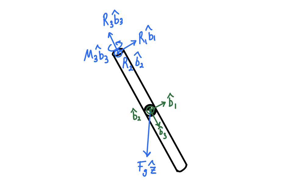
It is important that we include the reaction moment \(M_3\) which acts to prevent the pendulum from twisting about its longitudinal axis. Also, we will model the pendulum as a thin rod of length \(l\) and mass \(m\). Notice that the axes of the body frame coincide with the pendulum’s axes of symmetry. This was not an arbitrary choice. Choosing the axes of the body frame as the axes of symmetry will greatly simplify the angular momentum balance equations as will be shown later.
The next step is to perform a linear momentum balance in each of the coordinate directions of the body frame. But before we do so, we must derive an expression for the inertial acceleration of the center of mass of the pendulum in terms of the unit vectors of the body frame. The advantage of doing the linear momentum balance in the body frame is that the expression for the inertial acceleration is greatly simplified. To obtain an expression for the acceleration, we can differentiate the position vector \(\mathbf{r}_G/O=\frac{l}{2}\hat{b}_3\) twice:
\[{}^I\mathbf{a}_{G/O}=\frac{l}{2}[(\ddot{\phi}+\dot{\theta}^2sin(\phi)cos(\phi))\hat{b}_1+(\ddot{\theta}cos(\phi)-2\dot{\theta}\dot{\phi}sin(\phi)\hat{b}_2-(\dot{\phi}^2-\dot{\theta}^2cos^2(\phi))\hat{b}_3]\]Now we write the linear momentum balance equations in each of the basis vector directions.
In the \(\hat{b}_1\) direction:
\[\frac{l}{2}(\ddot{\phi}+\dot{\theta}^2sin(\phi)cos(\phi))=\frac{1}{m}(R_1-cos(\theta)sin(\phi)F_g)\]In the \(\hat{b}_2\) direction:
\[\frac{l}{2}(\ddot{\theta}cos(\phi)-2\dot{\theta}\dot{\phi}sin{\phi})=\frac{1}{m}(R_2-sin(\theta)F_g)\]In the \(\hat{b}_3\) direction:
\[-\frac{l}{2}(\dot{\phi}^2+\dot{\theta}^2cos^2(\phi))=\frac{1}{m}(-R_3+cos(\phi)cos(\theta)F_g)\]Next, we perform the angular momentum balance. Because we chose the pendulum’s axes of symmetry as the axes of the body frame, the inertia tensor is diagonal:
\[I= \begin{bmatrix} ml^2/12 & 0 & 0 \\ 0 & ml^2/12 & \\ 0 & 0 & 0 \\ \end{bmatrix}\]When the body frame’s axes coincide with the body’s axes of symmetry, these axes are called the principal axes. Also, we have used the fact that, because the rod is thin (\(r<<l\)), the moment of inertia about \(\hat{b}_3\) is negligible.
We also need the angular velocity vector in the body frame. The angular velocity of frame \(B\) with respect to frame \(I\) is:
\[{}^I\mathbf{\omega}^B=-\dot{\theta}\hat{x}+\dot{\phi}\hat{a}_2\]From here, we just use the transformation matrices we previously derived to express the angular velocity vector in terms of \(\hat{b}_1\), \(\hat{b}_2\), and \(\hat{b}_3\):
\[{}^I\mathbf{\omega}^B=-\dot{\theta}cos(\phi)\hat{b}_1+\dot{\phi}\hat{b}_2-\dot{\theta}sin(\phi)\hat{b}_3\]Now we can write the equations for the angular momentum balance about the center of mass of the pendulum with respect to the body frame. This implies that we must compute the moment exerted by external forces about the center of mass. Like with the linear momentum balance, we consider the angular momentum in each of the basis vector directions separately.
In the \(\hat{b}_1\) direction:
\[\frac{ml^2}{3}(-\ddot{\theta}cos(\phi)+\dot{\theta}\dot{\phi}sin(\phi))+\frac{ml^2}{3}\dot{\theta}\dot{\phi}sin(\phi)=\frac{l}{2}R_2\]In the \(\hat{b}_2\) direction:
\[\frac{ml^2}{3}\ddot{\phi}+\frac{ml^2}{3}\dot{\theta}^2sin(\phi)cos(\phi)=\frac{-l}{2}R_1\]In the \(\hat{b}_3\) direction:
\[0=M_3\]It is important to note that, had we used a body frame that was not the principal-axes body frame, the equations for angular momentum balance would have been much more complicated due to the inertia tensor having nonzero off-diagonal terms.
Now we have system of 6 equations (3 from LMB, 3 from AMB) for 6 unknowns (\(R_1\), \(R_2\), \(R_3\), \(M_3\), \(\ddot{\theta}\), \(\ddot{\phi}\)). Unlike the maximal coordinates approach, we do not have a separate constraint equation. The constraint that the rod is rigidly attached to the base was already taken into account when we derived an expression for \({}^I\mathbf{a}_{G/O}\). Had we approached this problem using the maximal coordinates approach, we would have had an additional degree of freedom from a third rotation about \(\hat{b}_3\) by an angle \(\psi\) and added a constraint equation \(\dot{\psi}=0\) to our system of equations. Also, we would not have assumed that the pendulum had a fixed length when deriving an expression for \({}^I\mathbf{a}_{G/O}\) and instead would have added a second constraint equation \(x^2+y^2+z^2=l^2\) to our system of equations.
Next step is to solve for the unknowns. To do this, I used MATLAB’s symbolic toolbox to write down the six equations symbolically, then used the solve function to solve for the six unknowns. Then I stored \(\ddot{\theta}\), \(\ddot{\phi}\), \(\dot{\theta}\), \(\dot{\phi}\) into a vector, turned it into a MATLAB function using matlabFunction, and plugged it into the ode45 solver to solve for the motion of the pendulum.
The resulting animation of the pendulum with various initial conditions are below:
As a sanity check, I plotted the energy versus time plot for the pendulum for the initial conditions corresponding to the second video:
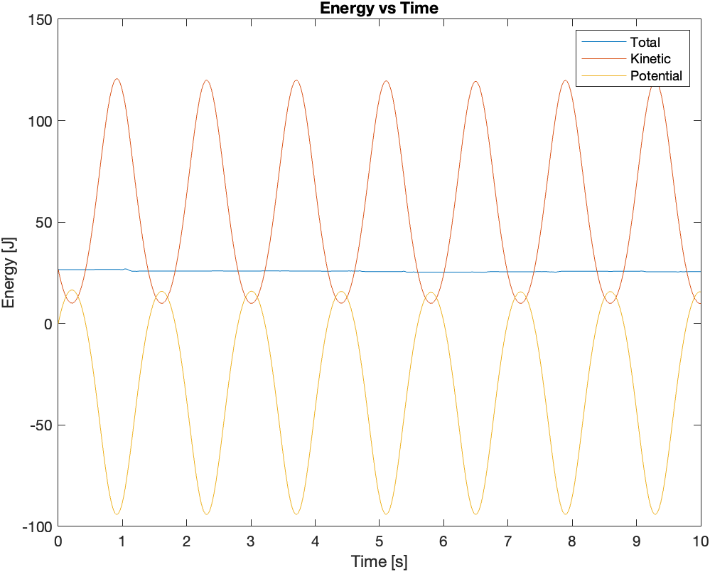
As you can see in the plot, the total mechanical energy stays approximately constant. It does not exactly stay constant due to numerical errors. I also noticed that giving the pendulum a large initial angular velocity amplifies the numerical error that accumulates over time.
Lagrange Method
The Lagrange method is much simpler than the Newton-Euler method. The Lagrangian of a system is defined as follows:
\[L = T - V\]where \(L\) is the Lagrangian of the system, \(T\) is the kinetic energy of the system, and \(V\) is the potential energy of the system.
For the single compound pendulum system, the kinetic energy is given by:
\[T = \frac{1}{2}m(v_x^2+v_y^2+v_z^2)+\frac{1}{2}(I_1\omega_1^2+I_2\omega_2^2+I_3\omega_3^2)\]\(I_1\), \(I_2\), \(I_3\) are the moments of inertia of the pendulum about the \(\hat{b}_1\),\(\hat{b}_2\),and \(\hat{b}_3\) directions, respectively. \(\omega_1\), \(\omega_2\), \(\omega_3\) are the angular velocity components in the \(\hat{b}_1\),\(\hat{b}_2\),and \(\hat{b}_3\) directions, respectively. \(v_x\), \(v_y\), \(v_z\) are the velocity components of the center of mass of the pendulum in the \(\hat{x}\), \(\hat{y}\), \(\hat{z}\) directions, respectively. The Cartesian coordinates of the center of mass of the pendulum are:
\[x = \frac{l}{2}sin(\phi)\] \[y = \frac{l}{2}cos(\phi)sin(\theta)\] \[z = \frac{l}{2}cos(\phi)cos(\theta)\]We can differentiate the three equations to get the three velocity components:
\[v_x = \frac{l}{2}\dot{\phi}cos(\phi)\] \[v_y = -\frac{l}{2}\dot{\phi}sin(\theta)sin(\phi)+\frac{l}{2}\dot{\theta}cos(\theta)cos(\phi)\] \[v_z = -\frac{l}{2}\dot{\phi}cos(\theta)sin(\phi)-\frac{l}{2}\dot{\theta}sin(\theta)cos(\phi)\]The three moments of inertia terms and the angular velocity components were already discussed in the previous section.
Next, we need to obtain an expression for the potential energy of the pendulum:
\[V = -mgz=-\frac{mgl}{2}cos(\phi)cos(\theta)\]Now we have an expression for the Lagrangian:
\[L=\frac{ml^2\dot{\phi}^2}{6}+\frac{ml^2\dot{\theta}^2cos(\phi)^2}{6}+\frac{mglcos(\theta)cos(\phi)}{2}\]Once we have an expression for the Lagrangian, the equations of motion can be obtained by plugging in \(L\) into the Euler-Lagrange equation:
\[\frac{d}{dt}\left(\frac{\partial L}{\partial \dot{q}_i}\right)-\frac{\partial L}{\partial q_i}=0\]where \(q_i\) are the generalized coordinates of the system. For our system, we have two generalized coordinates \(q_1=\theta\) and \(q_2=\phi\). Plugging \(L\) into the Euler-Lagrange equation will give us two equations (one containing \(\ddot{\theta}\) and one containing \(\ddot{\phi}\)).
Again, we can use MATLAB to do all of the heavy lifting for us. As we’ve done before, we can take the two equations and solve for \(\ddot{\theta}\) and \(\ddot{\phi}\) using the solve function. Then store \(\ddot{\theta}\), \(\ddot{\phi}\), \(\dot{\theta}\), \(\dot{\phi}\) into a vector, turn it into a MATLAB function using matlabFunction and plug it into ode45 to solve for the motion of the pendulum.
I was able to confirm that the equations of motion obtained using the Lagrange method matched the ones I obtained using the Newton-Euler method. As a result, the animation rendered using the Lagrange method was identical to the one rendered using the Newton-Euler method.
Tips for Animating the Solution
To animate the solution, I wrote a function that creates a cylindrical patch object at the desired orientation \((\theta\),\(\phi\)). This function takes five arguments: (1) Starting point of the cylinder, (2) radius of the cylinder, (3) length of the cylinder (4) \(\theta\), and (5) \(\phi\). My advice is to first create the cylinder using the cylinder function (which basically generates a matrix containing the coordinates of the surface points of the cylinder), rotate it by the two angles \(\theta\) and \(\phi\), then turn it into a patch object using the patch function. You may want to consider writing a separate helper function for rotating the surface points of the cylinder. This will involve using the Rodrigues’ rotation formula.